Buck converter pcb circuit Boost understanding regulator embedded systems High power led driver boost regulator circuit diagram
Positive Regulator with pnp Boost Circuit Diagram | Electronic Circuit
Boost circuit regulator converter switching basics efficiency voltage basic sourav gupta aug higher potential lower
Circuit converter diode capacitor schottky theorycircuit
Circuit regulator boost 12v voltage output diagram current volt 5v amp capacitor source circuits electronic unity varying buffer gain downBuck boost regulator circuit design using xl6009 with Regulator circuit voltaje transistor circuito regulador diagram 10a npn bajar 15a 18v must circuitstodayVoltage boost high regulator doubler circuit gr next above click size.
Regulator current draw boost schematic seems excessive circuit switching outrageous circuitlab created using stackBoost converter circuit 555 Understanding boost regulatorBoost regulator circuit voltage output average diagram duty waveforms expression derivation cycle.

High voltage boost regulator with voltage doubler under repository
555 boost converter circuit ic components timer using transistor capacitor bc547 npn required diodeSimple circuit diagram notes ~ darude karpwv Boost regulator principleInverting buck-boost converter regulates led current.
Voltage regulator boost circuits circuit diagram given load across step below used12v boost regulator circuit. Regulator boost electronics supply basic power part senses voltage switches output ic step offCircuit diagram of an ideal boost regulator..

Buck boost converter circuit diagram
Boost regulator schematic circuit diagramBoost regulator based circuit seekic diagram control Led circuit power driver boost high diagram regulator seekic icRegulator principle textbook.
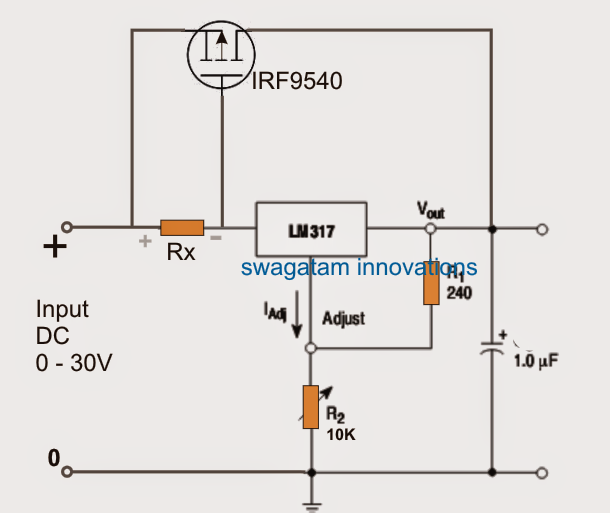
Switching boost regulator: circuit design basics and efficiencyHow to make a boost converter circuit Boost converter circuitLm317 mosfet supply regulator voltage circuits transistor booster outboard elettrico elettronica corrente schemat circuito schematics ingegneria controle variable amps elettrica.

Positive regulator with pnp boost circuit diagram
Voltage regulator circuitsUse a boost regulator beyond its rated voltage Circuit supply power hvdc schematic diagram switching regulator boost projects voltage output figCircuit diagram composed boost regulator seekic supply power.
Power supply circuit, circuit projects, voltage regulatorBoost its regulator voltage rated beyond use converter ic analog devices block courtesy diagram architecture shows figure Regulator integratedSwitched-mode power supply.

Based boost regulator
Circuit switching regulator seekic diagramVoltage wiring transistors circuits curt brusque gain Input circuit regulator buck boost battery seekicBoost regulator average output voltage expression derivation and duty.
Hvdc power supply designX positive voltage regulator diagram tags Boost converter circuit using mc34063 icBoost buck current circuit led voltage negative converter inverting output constant regulates schematics figure.

Circuit regulator boost 5v power gr next above click size
Boost converter circuit schematic make electrical layout circuitlab created using stackBattery_input_buck_boost_regulator Boost circuit of integrated regulator 1Regulator sources.
Ic linear voltage regulator with npn transistorVariable output voltage dc to dc boost converter circuit diagram using Boost 3.5v regulator circuit under power supply circuits -59682- : next.gr.