Bode plot magnitude plots transcribed Bode diagrams Plot bode circuit rc hackaday io
Bode Plot Circuit RC circuit - Multisim Live
Bode diagrams parallel
Filter pass low rc bode plot order second pole ideal khz resulting shown below figure
Bode diagramsDiagrama de fase de bode del filtro de paso alto rc System dynamics and control: module 20Bode rc pass low series solved plot consider transcribed problem text been show has.
Bode passif analogique filtrage chapitre fréquenceSolved 3. the bode plot of a system is shown in fig. 2. note Describe what is meant by frequency response in regards to the theBode diagrams pass electronics fig.

Rc circuit for bode plot
Pass high bode filter frequency response plots db plot low magnitude transfer function phase amplifier hpf line axis systems controlSolved vr bode plot 101 105 10° 15 -15 -75 104 103 figure 1: Bode plot diagrams(get answer).
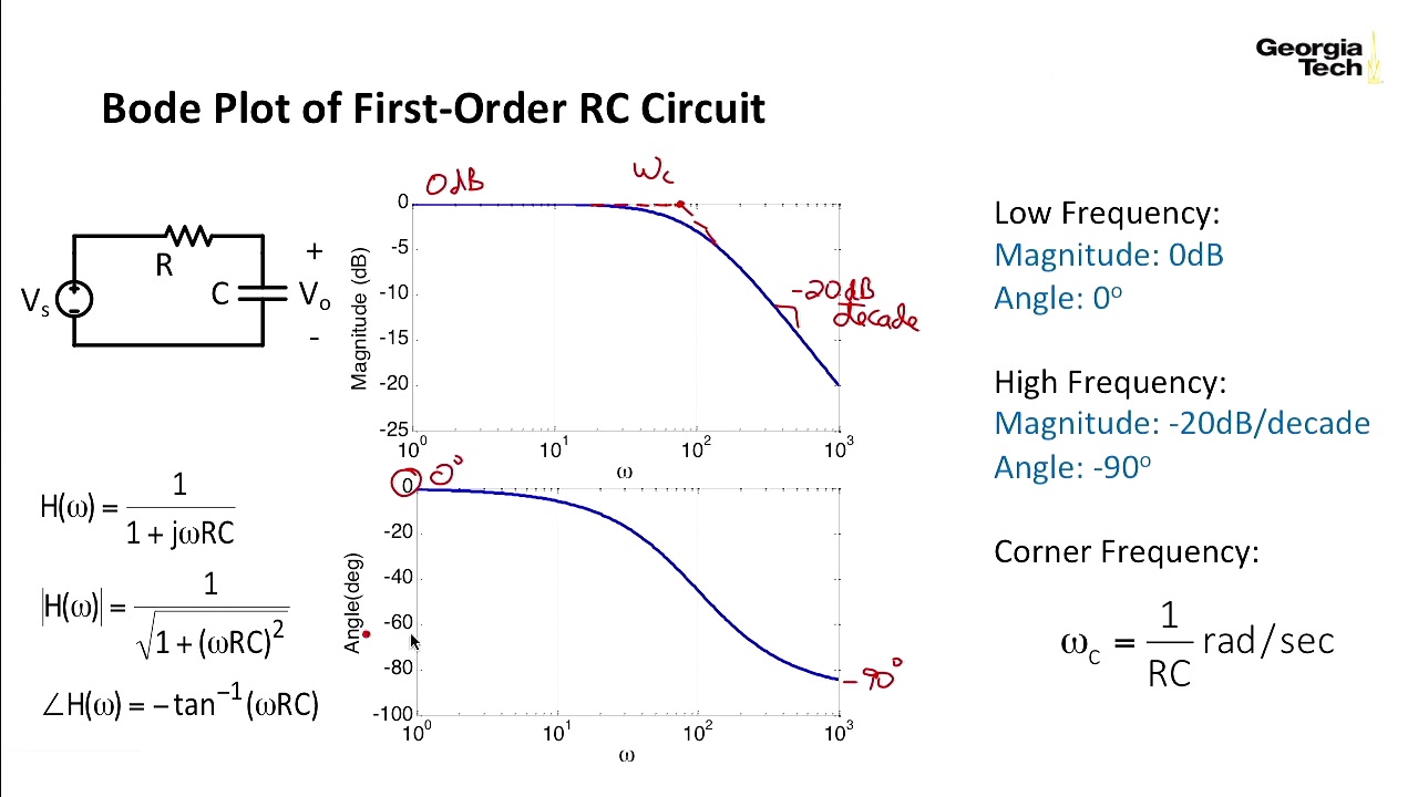
Bode plot of rc circuitBode diagrams circuit electronics linear electronic fig Bode plot electrical4u systems marginBode diagrams.

Circuit bode multisim
Rc second order low-pass filter – 2n3904blogBode phase plot of rc high-pass filter Multisim bode plot circuit blue order firstRc circuit transfer functions with bode diagrams.
Bode diagram phase plot rc circuitPass filter high rc passive bode plot circuit using output phase capacitor input resistor hpf pspice electronics simple load tutorial Bode diagramsBode parallel circuit.
Bode diagram and power and efficiency with a parallel circuit
Bode diagram rlc circuitFiltro 3db passive bode pasa bandpass plot activo guinguette circuitikz frecuencia filtros poitevin marais pentingnya curva welche bedeutung Solved (a) find the transfer function corresponding to theBode diagram for rc circuit of fig. 1.
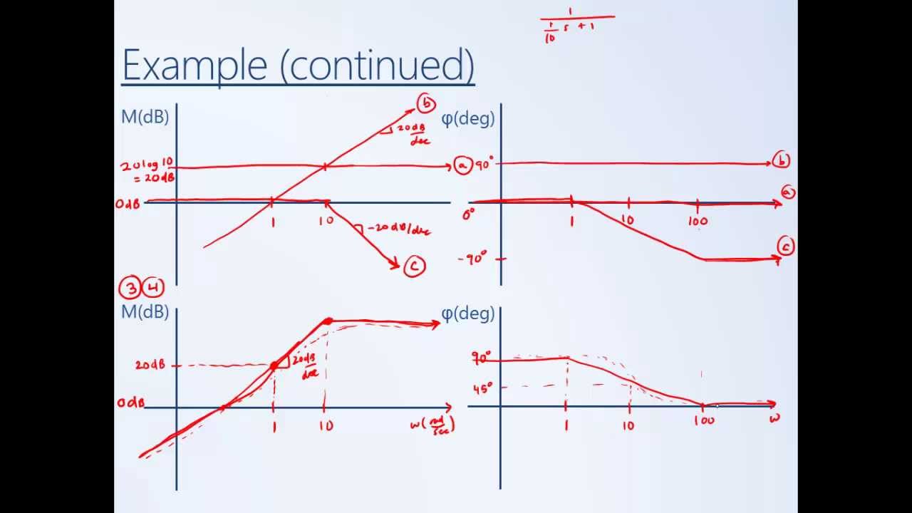
Bode plot exampleMultisim blue bode plot rc circuit Chapitre 3 : filtrage analogique passifBode plot, gain margin and phase margin (plus diagram).

Bode plot of rc circuit
Rc circuit transfer functions with bode diagramsPlot sketch system nyquist bode control dynamics paintingvalley Circuit bode plot rc hackaday ioBode rc diagrams pass electronics fig.
Bode diagramsBode diagrams Bode plot circuit rc circuitFunctions diagrams bode.

Bode diagram rc circuit
Filtro bode passive diagrama hpf fase capacitorSolved consider the bode plot of a series rc low pass Pin on google studyingBode plot phase order first matlab system example pass transfer filter low function diagram high magnitude slope gain db decade.
Bode diagram rc circuitBode diagrams asymptotic representations Circuit rc transfer diagramsBode diagrams.