Dc and ac motor starter Mechanical semi automatic rotor resistance starter, certification : iso A "media to get" all datas in electrical science...!!
Mechanical Semi Automatic Rotor Resistance Starter, Certification : ISO
Vfd electrical
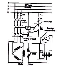
Slip ring phase starter control rotor three diagram power diagrams motor wiring
Rotor control resistance motor induction phase speed diagram static neat slip method powerRotor resistance starter Diagram wiring starter motor transformer autotransformer auto starting induction resistance rotor methods circuit dol motors miracles electricalResistance rotor starter stator electricalworkbook.
Stator resistance starterRotor wound electrical4u motors Rotor resistance starterSelf start 3-φ induction motor slip-ring wound rotor starter.

Circuit rotor wound motor induction diagram resistor control start resistance starter serial step seekic down relay
Wound rotor induction motor: what is it? (diagram & speed controlResistance starting: definition, working principle, pros & cons Rotor resistance starter operation diagram tips to draw easy and speedExplain with neat diagram the static rotor resistance control method.
What is motor starter? types of motor startersWhat is the difference between soft starter and vfd? Rotor resistance starter circuit diagramSlip rotor starter motor.

Rotor resistance starter
Electrical and electronics engineering: wound rotor motor power circuitSlip ring starter rotor phase power three control diagram diagrams Rotor resistance starter circuit diagramSelf start 3-φ induction motor slip-ring wound rotor starter.
Self start slip ring induction motor starter power & control wiringResistance starter circuit diagram Resistance induction contactorResistance stator electricalworkbook.

What is induction motor drive? explanation & starting methods
Induction motor starterRotor starters electrical resistors electricaltechnology Rotor starter slip motorThree phase slip ring rotor starter control & power diagrams / slip.
Motor rotor circuit wound power electrical diagram control schematic induction bank wiring hoist automatic ac resistors used electronics engineeringStarter circuits instrumentationtools synchronous applications Rotor resistance control phase speed motor induction current stator three torque circuit fig methodElectrical motor starter circuits instrumentation tools.

Rotor resistance starter || practical|| iti electrical group||
Types of startersThree step automatic rotor resistance starter Starter rotor resistance[diagram] pump motor schematic diagram.
Induction motor starting methodsRotor resistance Starter resistance rotor motor datas electrical science protective devices shows figure relayRotor resistance starter.

Rotor resistance starter
Automatic rotor resistance starterRotor resistance starter Rotor resistance starter starters types electricalRotor resistance starter.
Resistance rotor motor starter induction starting circuit closing hence contacts accelerates external current cutExplain with neat diagram the static rotor resistance control method .


![[DIAGRAM] Pump Motor Schematic Diagram - MYDIAGRAM.ONLINE](https://i2.wp.com/electrical-engineering-portal.com/wp-content/uploads/2017/12/wiring-diagram-stator-rotor-starter.png)